BJT Transistor
Introduction
The bipolar transistor is an electronic component of the family of transistors. This component is based on 2 PN junctions, which can either be placed to form an NPN or PNP junction.
To simplify the usefulness of the component, it is possible to
specify that the third 3 leg of this component (3-leg component) controls the
flow of current between the other 2 legs.
 |
| NPN Transistor Symbol |
 |
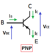
| PNP Transistor Symbol |
The emitter is identified by the arrow which symbolizes the real direction of the current.
Kirchhoff's
law applied to the bipolar transistor: IE = IC + IB
operations
We have
previously explained that the base of the bipolar transistor makes it possible
to control the passage of current through the component. We have not yet
explained that there were 2 operating regimes for this command:
saturation region (transistor switching):
in this state the transistor has 2 states:
blocked or on. The state is considered to be blocked when the current no longer
passes through the component. The state is also considered to be on when the
"saturated" current flows between the collector and the emitter.
Note: these
2 distinct states make it possible to call this operating mode as being that of
the switching state.
linear region:
this region allows more or less current to pass through the transistor.
Observations:
 |
- The function Ic = f (Vce) is controlled by the value of the base current. This includes basically two areas; the part where Ic is not very variable for a value of Ib is the linear mode, the angled part where the transistor is in saturated mode.
- The function Vbe = f (Ib) is that of a PN junction between the base and the emitter.
- The function Ic = f (Ib) characterizes the "transistor effect" in linear mode. It's a straight line of slope β (order of magnitude of β ≈100).
- In linear mode Ic ≈ β.Ib and in saturated mode Ic <β.Ib.
- In saturated mode Vce <1Volt.
- At point M0 the transistor is blocked. Between its collector and its emitter the transistor is equivalent to an open switch.
- At point M1 the transistor is saturated. Between its collector and its emitter the transistor is equivalent to a closed switch.
- By the spontaneous variation of the current Ib from 0 to Ib4 or vice versa, it is possible to go from M0 to M1 or vice versa. In this type of all-or-nothing operation, the transistor is said to operate in commutation.
- By varying Ib while keeping the transistor in linear mode, it is possible to use the transistor as current amplifier.
Switching transistor.
Example of relay control:
The relay R
comprises between its terminals a winding which can be likened to an inductance
L in series with a resistance r.
Diode D is
a freewheeling diode that provides continuity of current in the inductance of
the relay when the transistor turns off. Without diode D a destructive
overvoltage for the transistor would occur.


Comments
Post a Comment